Connecting design and measurement
This will dramatically change the way you do measurement.
If you want to streamline your measurement work, pay attention to the design process. By simply adding tolerance information to the 3D CAD model,
"MiCAT Planner," the CMM automatic measurement program generation software, generates a measurement model with one click.
While the traditional method of programming using 2D drawings takes 45 to 60 minutes, and even the method using 2D drawings and 3D CAD takes 15 to 20 minutes, using MiCAT Planner it can be completed in about 3 minutes.


The optimization function enables the software to determine the minimum number of probe orientation changes and tool changes, as well as the shortest measurement path, to generate a program that enables measurements to be completed in the shortest time.


Reducing measurement time makes it possible to greatly improve the efficiency of measurement work!
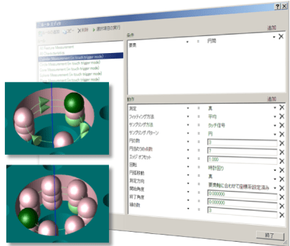
By setting measurement rules using the rule editor function, measurement paths are automatically generated according to the rules, preventing quality variations between programmers.
By setting measurement rules, measurement paths are automatically generated according to the rules, so there is no variation between programmers.
The MiCAT Planner screen is made up of simple views that can be operated intuitively, such as 3D view and plan view. The layout and window size can be freely customized.
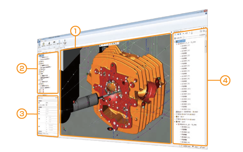
| ① 3D View | Displays information graphically. - Measuring machine information - CAD model, tolerance information - Measurement points, measurement paths - Measurement animation |
|---|---|
| ② Plan View | - Displays a list of measurement elements, tolerances, etc. ・You can select whether or not to measure or evaluate by checking the checkbox. |
| ③ Property View | It is possible to change the names of elements, tolerance items, and measurement points, and to edit measurement points for each individual element. |
| ④ Program View | - Displays measurement details and estimated measurement time. Animation feature allows you to perform animations of your measurements in the 3D view. |
| CAD format | extension |
|---|---|
| ACIS | .sat |
| STEP | .step/ .stp |
| NX | .prt |
| Creo Parametric (Pro/E) | .prt/ .prt. |
| CATIA v5 | .CATPART |
| Solid Works | .sldprt |
[Supports 15 languages]
Japanese, English (US/UK), German, French, Spanish, Portuguese, Italian, Chinese (Simplified/Traditional), Korean, Polish, Czech, Dutch, Turkish, Russian